Wiring & Connectivity
This chapter details the physical connections required to interface the STM32F411 (Black Pill) with your host machine and external hardware master devices.
1. Hardware Overview
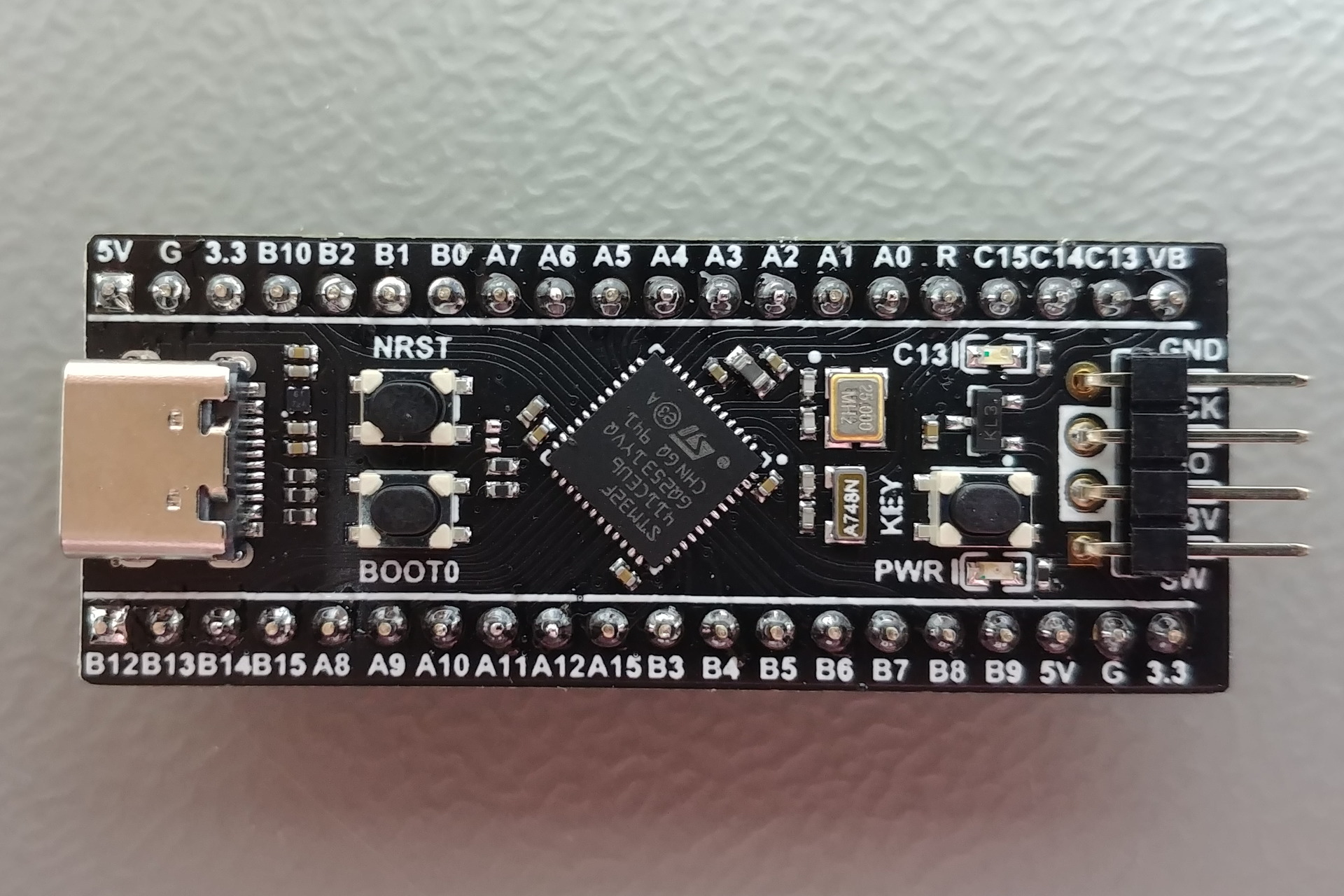
The STM32F411CEU6 Black Pill is the core processing unit for Mimic. Below is a real-world view of the board's top side, showing the MCU, crystal, and breakout pins.
2. Programming Interface (ST-Link v2)
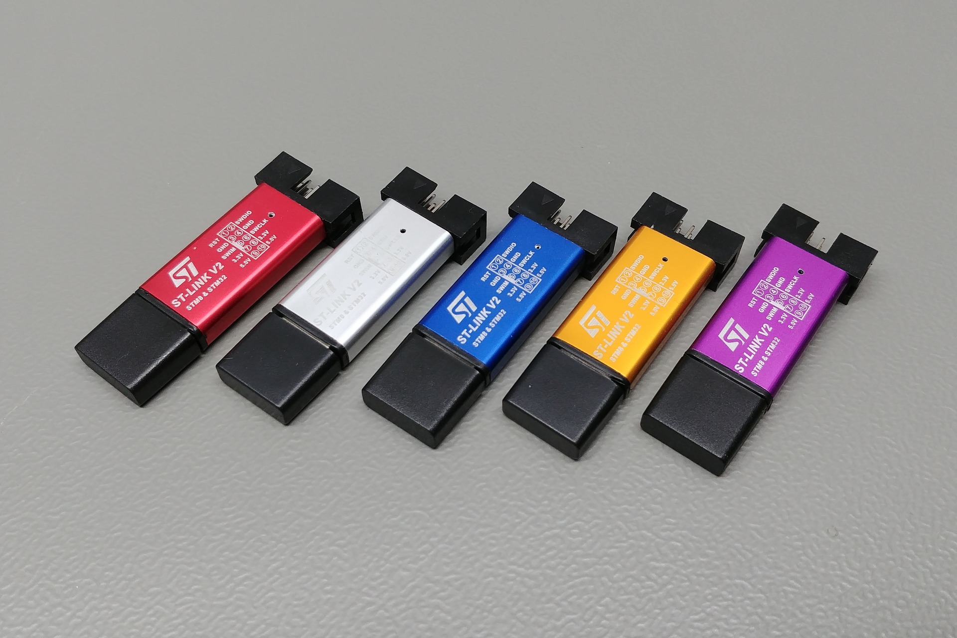
The primary method for deploying Mimic Firmware is via an ST-Link v2 programmer. The real-world hardware typically comes in a small USB-stick form factor as shown below.
Connection Table
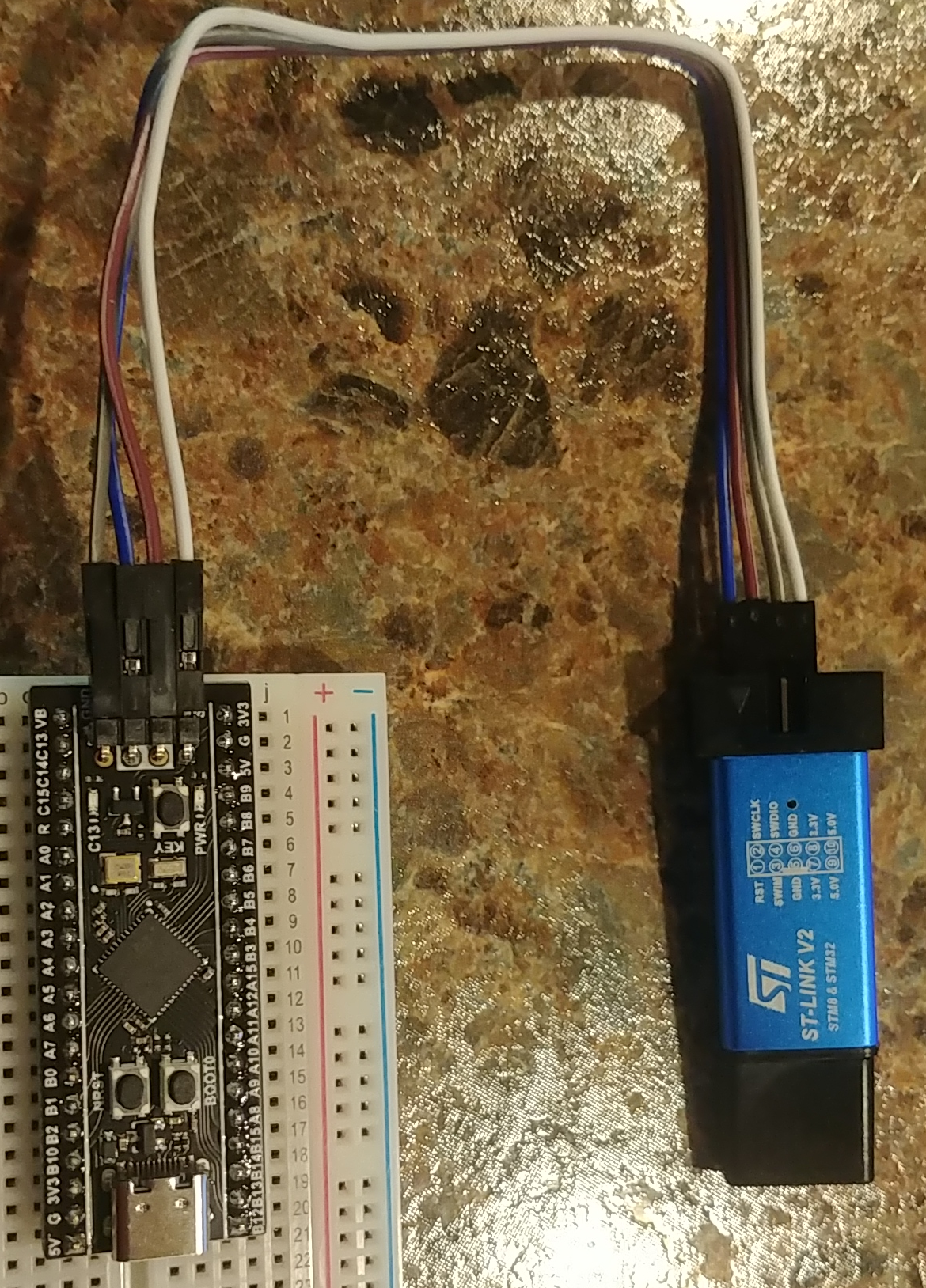
| ST-Link Pin | Black Pill Pin | Description |
|---|---|---|
| 3.3V | 3.3V | Target Power |
| GND | GND | Common Ground |
| SWDIO | DIO / PA13 | Data Line |
| SWCLK | CLK / PA14 | Clock Line |
3. Host Communication via TTL (UART2)
In cases where the USB-C port is not used for host communication, a USB-to-TTL converter (typically using the CP2102 chip) can be connected to UART2 to provide full CLI control.
Bridge Connection (TTL)
| Converter Pin | Black Pill Pin | Description |
|---|---|---|
| TX | PA3 (RX2) | Data from Host to MCU |
| RX | PA2 (TX2) | Data from MCU to Host |
| GND | GND | Common Ground |
4. Peripheral Hardware Mapping
To emulate sensors correctly, ensure your Master device (e.g., Raspberry Pi or Arduino) is connected to the following hardware ports on the Black Pill:
UART (GPS Emulation)
- TX (Master) -> RX (PA10)
- RX (Master) -> TX (PA9)
- GND -> GND
I2C (MPU6050 Emulation)
- SCL: PB6
- SDA: PB7
SPI (BMP280 Emulation)
- SCK: PA5
- MISO: PA6
- MOSI: PA7
- CS: PA4